Pinball Machine
*Awarded one of the Top 5 Projects in the class*
The Pinball Machine is a project that myself and three other mechanical engineering students completed for our Mechatronics Course Project. This was the first major project that I worked on that involved a large amount of electrical engineering and programming, which proved to be a steep learning curve for me. I am proud that my team and I were able to accomplish such an ambitious project and overcome the many challenges that we were faced with along the way.
PROJECT OVERVIEW
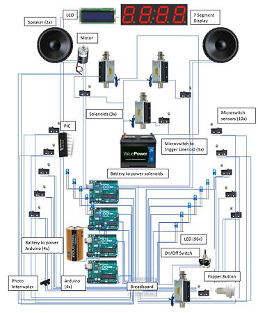
The Pinball Machine project is a simple take on the beloved arcade game, featuring all the popular components of a real pinball machine. It is housed in a wooden chassis and is comprised of 96 LED lights, a seven segment display, an LCD screen, an ultrasonic sensor, a photointerrupter, speakers, a buzzer, 17 micro switches, a motor, 3 pop bumpers, 5 solenoids, and 2 flippers. All the components were programmed and wired together through the use of four arduinos and a PIC 16f88. Most of the physical components located on the playing field were 3D printed to make the game more interactive and functional. A labeled drawing of the pinball machine with all the major elements can be seen below, as well as the 3D view.


GAMEPLAY
To turn the system on, a switch found on the front of the machine is flipped on, which initiates a light show and music to introduce the game. Subsequently, the LCD will display “START GAME” as soon as the switch is flipped and the integrated system receives power. 72 LEDs were lined along the border of the pinball machine and loop through their designated show throughout the game. The remaining 24 LEDs, which are found on the playing field, begin running through their own sequence. Once the song that is played when the initial "ON" switch is flipped ends, the motor at the top of the board begins its rotation. The motor is attached to a 3D printed component that will interfere with the pinball’s path and launch it into target micro switches. After a specified amount of time, the LCD will go blank, and a coin can be inserted into the slot in the front of the board. The photointerrupter is strategically placed behind this slot to detect the insertion of the coin. Once interrupted, the LCD will display “Player 1 Ball 1,” and the game is ready to play. The player will then drop the pinball into the channel containing the plunger mechanism. Micro-switches are located throughout the playing field where points will be added to the seven segment digit display and cause a buzzer to go off. Points are also added to the score when the pop bumpers are activated. To control the flippers, the player can push a button located on the right and left side of the pinball machine, which are operated by solenoids. Every time the ball falls past the flippers, it will roll into a tube where the ball can be collected by the user. Right before it passes through the tube, an ultrasonic sensor will detect the ball rolling by, which in turn will display, “Ball 2,” “Ball 3,” and “Game Over” on the LCD. Once the third ball passes the sensor and “Game Over” is displayed, the score will reset to 0 points. The flowchart of how all these components work in unison can be found in the below, as well as their wiring diagrams.

MAIN COMPONENTS
LED Lights
The LED circuit controls a total of 72 lights, using a total of 36 pins. In order to accommodate for all of these pins, an Arduino Mega was used. Each side of the playing field was lined with these 36 lights. Each LED, sharing a common supply with the LED across from it, were put in series with each other. At the center of these connections, a resistor was attached to ensure that the light did not receive a voltage higher than what it was allowed. The other end of the resistor was then attached to another wire, which received its own designated pin in the Arduino Mega. Every LED shared a common ground as well, which was then grounded in the Mega. The Arduino received power from a 9V battery, which was turned on using the on/off switch.

The PIC circuit, which controlled another 24 LEDs mounted on the playing field itself, can be seen in Figure 6. The PIC was coded for 12 LEDs, which were again placed in series with another 12 lights. Each of the lights shared a common ground. Resistors were not needed in series with these LED’s. Rather, only one resistor was included in the circuit, which was connected from power to the PIC itself. Holes were drilled in the playing field in the shape of a “V,” and the lights were inserted.
Solenoids
Solenoids were used in the pop bumper and the flipper components of the game. Each solenoid was connected to either a micro switch or leaflet switch, which ensured that the solenoid was not receiving constant current. When a certain switch is closed, it activates the desired solenoid to complete its function. Two solenoids were used for the flipper mechanism, and another three solenoids were used for the pop bumper assembly. The switches for the pop bumpers were also connected to the micro switch circuit, which will add score to the 7 segment display each time it is pressed.

7 Segment Display
The 7 segment display is made up of 8 wires which are connected to an Arduino. The display included on the pinball machine is made up of 4 numerical spots, allowing for a maximum score of 9,999 to be reached. This circuit is also integrated with that of the micro switches to ensure that each time they are pressed, a point will be added to the score. The 7-segment display was mounted on the headboard of the pinball machine. A rectangular slot was cut for the display to rest in, and the wires were guided down the back of the machine and through a drilled hole at the bottom, This provided the ability to connect the display to the existing circuits beneath the playing field. For aesthetic appeal and safety, all of the wires that were guided down the back of the machine were electrical taped to the surface of the machine. This provided a simple way to control all of the wires.

Speakers
The speakers were integrated into the same circuit as multiple other components. At the beginning of the game, the an introduction song will play. After one duration of the song, it will not loop again. The two speakers were connected in series by connecting ones power with the other’s ground. Both speakers shared the same ground as the buzzer, microswitches, and motor. This song was integrated into the system for the entertainment of the player.

Micro-switches/buzzer
Within the circuit seen above, a buzzer and a series of microswitches are integrated. Each microswitch, when closed, triggers the buzzer to sound the tune coded to it. Everytime a micro-switch is closed, an additional point will be added onto the screen of the 7 segment display. They were each placed strategically throughout the playing field to ensure the ability to increase one’s score. Rollover switches, targets, and leaflet switches connected to the pop bumpers were all included in these functions.
LCD
Numerous components were integrated into this Arduino Uno as well. The LCD displayed various messages throughout the game to ensure that the player knew which ball they were on. This was mounted on the headboard of the pinball machine. A slot was cut from the board so that the LCD could be mounted. The wires were directed through the back of the board and back through a hole at the bottom of the machine. This allowed the wires to connect with the Arduino, which was housed inside the hollow chassis. All wires were electrical taped to the back of the board to ensure safety and maintain a sleek appearance.

Ultrasonic Sensor
The ultrasonic sensor, which can be found in the circuit above, was placed at the base of the ramp below the flippers. Each time the ball passed this sensor, it would communicate to the LCD to print a message on the screen. This was vital to the playability of the game because without it, there would be no beginning or end. Due to the ultrasonic sensor, the game allows the player three tries before their game is over and the score is re-set.
Photo Interrupter
The photo interrupter was stationed behind the coin slot. When a coin was inserted, it would interrupt the emission wavelength from reaching the optical receiver, communicating with the LCD to display the start of the game. Once this is done, the game is ready to play. The photo interrupter was attached to the wall itself, so that a quarter can roll through the slot between the two sensors. This can also be seen in the circuit above.
BOM
A large amount of supplies were needed to successfully implement a fully functional pinball machine. In the table below, the most significant parts are listed and include their model number (if applicable), where they were purchased or found, and the price required. As can be seen below, a majority of the parts were provided by past projects or the CSU ME Department. This was beneficial for the overall outcome of the project, as the price was kept at a low amount. While not all of the parts are included, the important components to the functionality of the machine have been included below.

FINAL OUTCOME
After many long nights and tireless weekends, my team and I successfully completed the project and produced a fully functioning pinball machine. The professor of the course was so impressed with the project that he awarded it as one of the Top 5 and asked us to present our final results to the class. Through the research, design, and building of the Pinball Machine, I learned so much about the integration, wiring, and programming of electrical components in a mechanical system, as well as the dedication and will it takes to complete a large scale project from start to finish.
.jpg)
.jpg)

LESSONS LEARNED
-
Though all of the wires in the inside of the machine were necessary, the wire management could have been cleaner. In the future, the use of shorter wires when possible would allow for a cleaner design as well as the use of velcro to hold multiple wires together while also allowing for them to be unattached would be better than the zip ties used on the machine.
-
For maintenance purposes, making the inside circuits more accessible would have benefited the design. Either creating a trap door at the rear of the machine or a hinge to hold the top portion up while alterations were being made inside the machine would have been better designs.
-
The use of LED strips would have made the light show on the border of the machine more robust. The pinball machine had each individual wire soldered together and had a total of 72 leds on either side of the machine. Time could have been saved if money was spent on a LED strip than just using the LEDs that were provided in the Arduino kit.
-
Arduinos are not very effective in converting analog to digital signals, so using a predetermined song and an SD card module proved to be difficult. It is best to use the Arduino tones library for quality sound and volume.
-
It may have been more beneficial to use a power cord than multiple batteries as power sources. The machine would have also been more lightweight without the 12V batteries inside of the system.
-
Purchasing a more robust motor would have allowed for the fan obstacle to spin faster with the given voltage output of the implemented motor. The motor that was used for the project was given by a friend and was used previously for another project.
